ICE PROTECTION, PROBE HEATING AND RAIN REMOVAL
Engine/wing anti-ice, window heating and probe heating protect different equipment through different sources. The supplied ice/rain description separates pneumatic heat for the engine/wing functions from electrical heating for windows and air-data probes. This matters when tracing failures: a loss of one bleed source is not the same event as loss of electrical probe heat, and a working window does not prove that all required sensing probes are protected. Identify the protected area and its actual source before interpreting an indication. [77, PDF pp. 2–7]
Probe heating supports valid air-data measurements, while the downstream consequences of corrupted air data can reach guidance, engine control, warning and flight-control functions. A pitot/static or angle-of-attack problem therefore deserves a source-based investigation rather than an assumption that a single PFD has failed. The actual warning, sensor validity, selected sources and control law matter. Reference operating thresholds, automatic heat logic and ground-test behaviour are standard-dependent; they are not restated here as universal Fenix temperatures or timings. [77, Protection-system description, probes/windows] [65, PDF pp. 3–5] [73, PDF pp. 27–33]
Pneumatic anti-ice demand also changes the performance configuration. The takeoff/landing assessment must describe the selected equipment, atmosphere and airframe; a later change can require revised performance data. Ground contamination removal remains a separate task from airborne protection. Selecting wing anti-ice does not establish a clean wing or substitute for a deicing/anti-icing process. The operational chapter deals with the weather decision and coordination; the systems question is what area the selection protects and what demand or configuration change it creates. [77, PDF pp. 3–7] [74, PDF pp. 8–9] [21, PDF pp. 277–278]
Wipers and rain-removal equipment have their own operating conditions and mechanical/electrical dependencies. Their presence on an overhead panel should not invite testing against an unknown dry/wet or speed condition. Ice-detection equipment, where documented as an installed option, adds information rather than removing the need to understand the actual icing situation and protected areas. In a simulator exercise, record which detection/heating options exist and which specific failures are represented. A visual icing effect alone does not independently validate a complete sensor, thermal or aerodynamic failure model. [77, Ice/rain system descriptions and equipment effectivity] [70, Available Options: fnx_ice_detection_enabled] [86, Failures Guide; implementation scope]
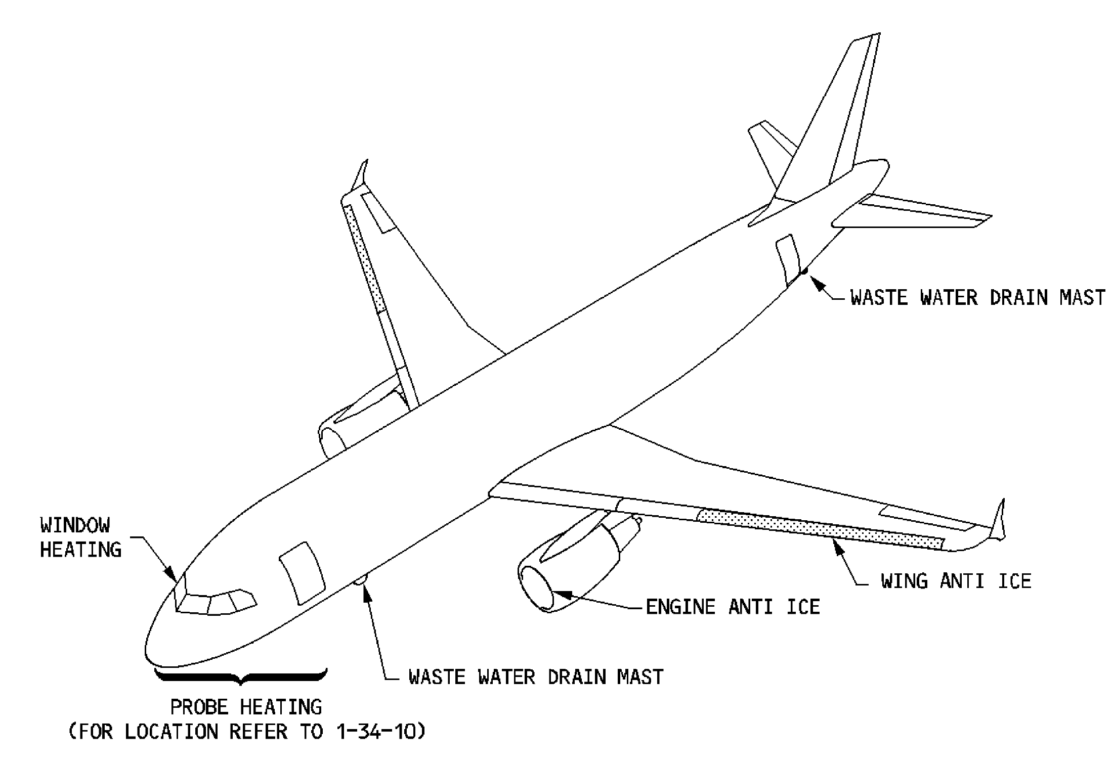
A320 wing, engine-inlet, window and probe protection locations. [77, PDF p. 2]