FIRE AND OXYGEN: MAKE THE TESTS DIAGNOSTIC
Use the designated fire-test controls and observe the required warning indications, sound and ECAM response. Confirm that the indications clear after release. Distinguish the test control from the guarded fire pushbuttons and extinguishing-agent controls; each has a specific function in the system. [78, PDF pp. 5–8] [23, PDF pp. 1016–1017]
The flight-deck oxygen supply and passenger system are separate. During normal preparation, use the installed crew-mask test, observe the required flow/test indications and restore the controls and stowage state correctly. Testing crew equipment does not call for operating the passenger-mask deployment control. [79, PDF pp. 2–8]
A completed test should leave an understood result: the expected warning occurred, the relevant indication appeared and the system returned to its normal state. If one part differs, investigate that difference before treating the test as complete. The value lies in the response observed, not in having pressed the control.
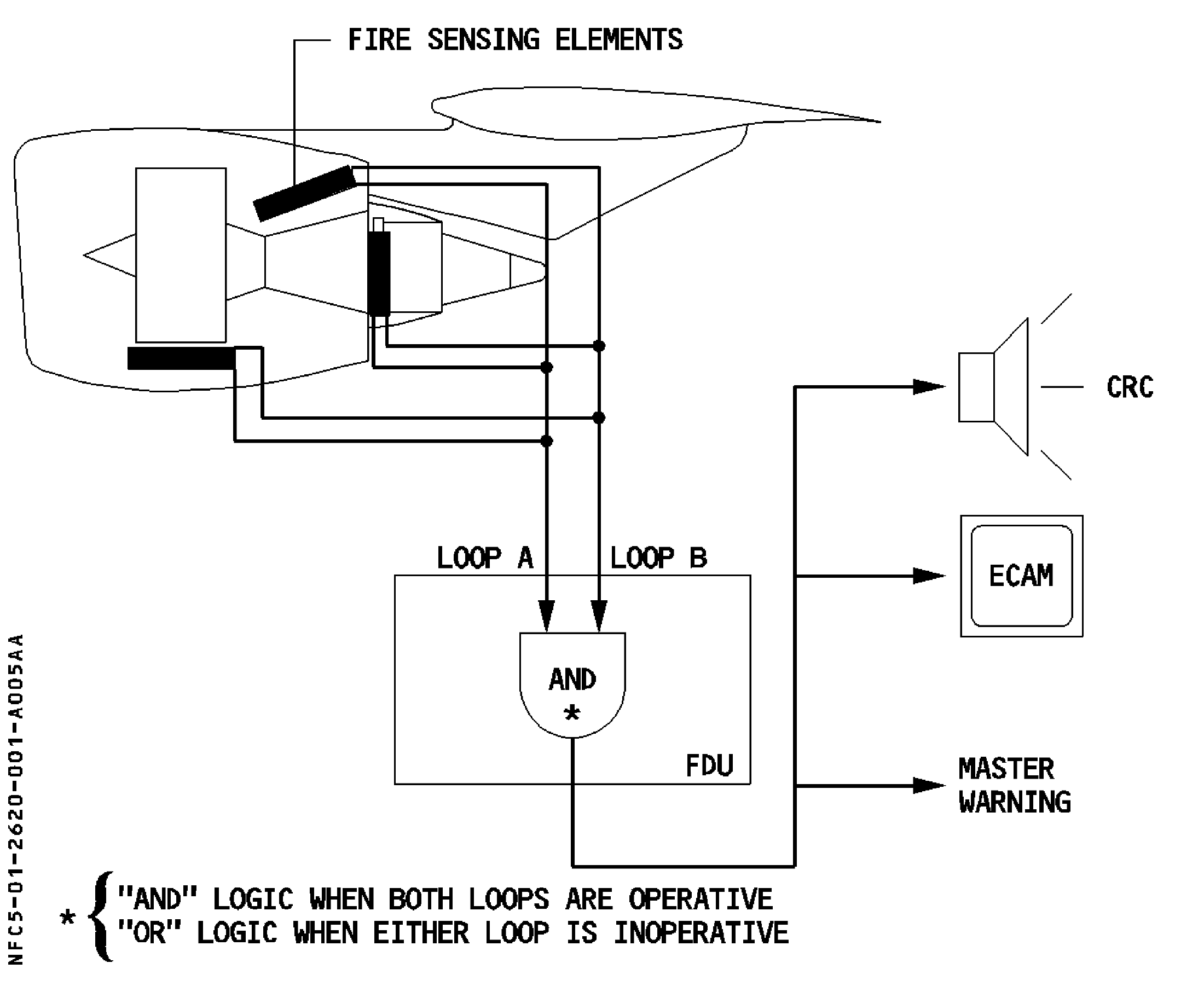
Engine fire-detection loops and the warning path. [78, PDF p. 3]
IN PRACTICE: Make the normal fire and oxygen tests diagnostic
Before you begin: Stable electrical power and the installed normal test instructions available. These are normal TEST controls, not fire-agent discharge or passenger-mask deployment commands. Match the instructions to the actual modeled unit.
1. Identify the controls and check oxygen supply
Action. Confirm the guarded fire controls in their normal positions and identify the actual TEST buttons. Check CREW SUPPLY and review crew-oxygen pressure on DOOR/OXY against the applicable current requirement.
Check. The test controls are distinguished from discharge/deployment controls, and the crew oxygen supply state is known. [23, PDF pp. 989,1016-1017,1030] [21, PDF pp. 92-93]
2. Test each engine fire circuit
Action. Press the ENG 1 TEST control and observe the corresponding ECAM fire warning, aural/master warning and fire-panel/engine FIRE indications, including SQUIB and DISCH test lights. Release, then perform the corresponding ENG 2 test.
Check. Each engine’s normal test produces its own expected indications. Check the panel’s normal state after release before moving on. [23, PDF pp. 1016-1017]
3. Test the APU fire circuit
Action. Press the APU FIRE TEST control and observe the APU FIRE warning, aural/master warning when AC power is available, red fire control and SQUIB/DISCH test indications. Release and verify the normal post-test state.
Check. The APU test has been checked separately from the engine tests and no agent-discharge control has been operated. [23, PDF p. 989]
4. Complete the installed normal oxygen test
Action. Use the normal mask-test procedure provided with the installed aircraft. Check its required flow and communication indications, then restore the mask and supply to the specified normal state.
Check. The oxygen-supply and mask-test checks are complete against the applicable procedure, with the equipment correctly stowed. [23, PDF pp. 1030–1031]
Complete when: The fire-test responses have been checked, oxygen supply verified and the installed normal mask test completed. Test controls are released and normal selections restored.