FLIGHT-CONTROL COMPUTERS, ACTUATORS AND REDUNDANCY
The reference flight-control architecture separates electrical command from hydraulic actuation. Two ELACs provide normal elevator/stabiliser and aileron functions; three SECs provide spoiler functions and specified backup pitch functions; two FACs support augmentation functions including yaw-related control and characteristic-speed information. Two SFCCs supervise high-lift functions, while data concentrators provide monitoring/presentation interfaces. Counting computers alone does not establish independence: their input sources, electrical feeds and hydraulic users also matter. [73, PDF pp. 2–8] [87, PDF pp. 54–55, 70–72]
The source describes control and monitoring channels with dissimilar redundancy. A computer may detect an internal fault or reject inconsistent input rather than fail as a completely silent box. The system can reconfigure control authority and surface availability when a component becomes unavailable. This means that an operational surface can remain visible while redundancy or control law has changed. Conversely, a failed actuator can affect a particular surface without establishing that the entire axis has no control. [73, PDF pp. 3–8, 27–33] [87, PDF pp. 70–72]
Elevators have separate powered actuation paths, and the trimmable horizontal stabiliser has a distinct control/drive arrangement. Ailerons, spoilers and rudder likewise have allocated hydraulic and computer dependencies. The aircraft’s handling after a failure therefore depends on the combination of surviving command logic and powered surfaces. A law reversion is a change in the relationship between pilot input and response/protection, not simply another name for hydraulic failure. Read F/CTL, PFD law/trim information and the remaining status together. [73, PDF pp. 6–18]
Family commonality does not make every control-standard detail identical. The current product description identifies variant-specific control/warning modifications; the historical documents describe their own effectivity. Use those documents to understand the mechanism, then establish the configured Fenix standard and available failure scenario. A desktop controller is another layer: duplicated axes or a mismatched calibration can create a false impression of unusual law behaviour. Validate hardware input and actual control movement before interpreting a handling difference as an airframe or protection-system feature. [52, Variant-specific ELAC/SEC/FAC/FWC/ECAM modifications] [75, Flight-control calibration] [73, Source effectivity and computer/control architecture]
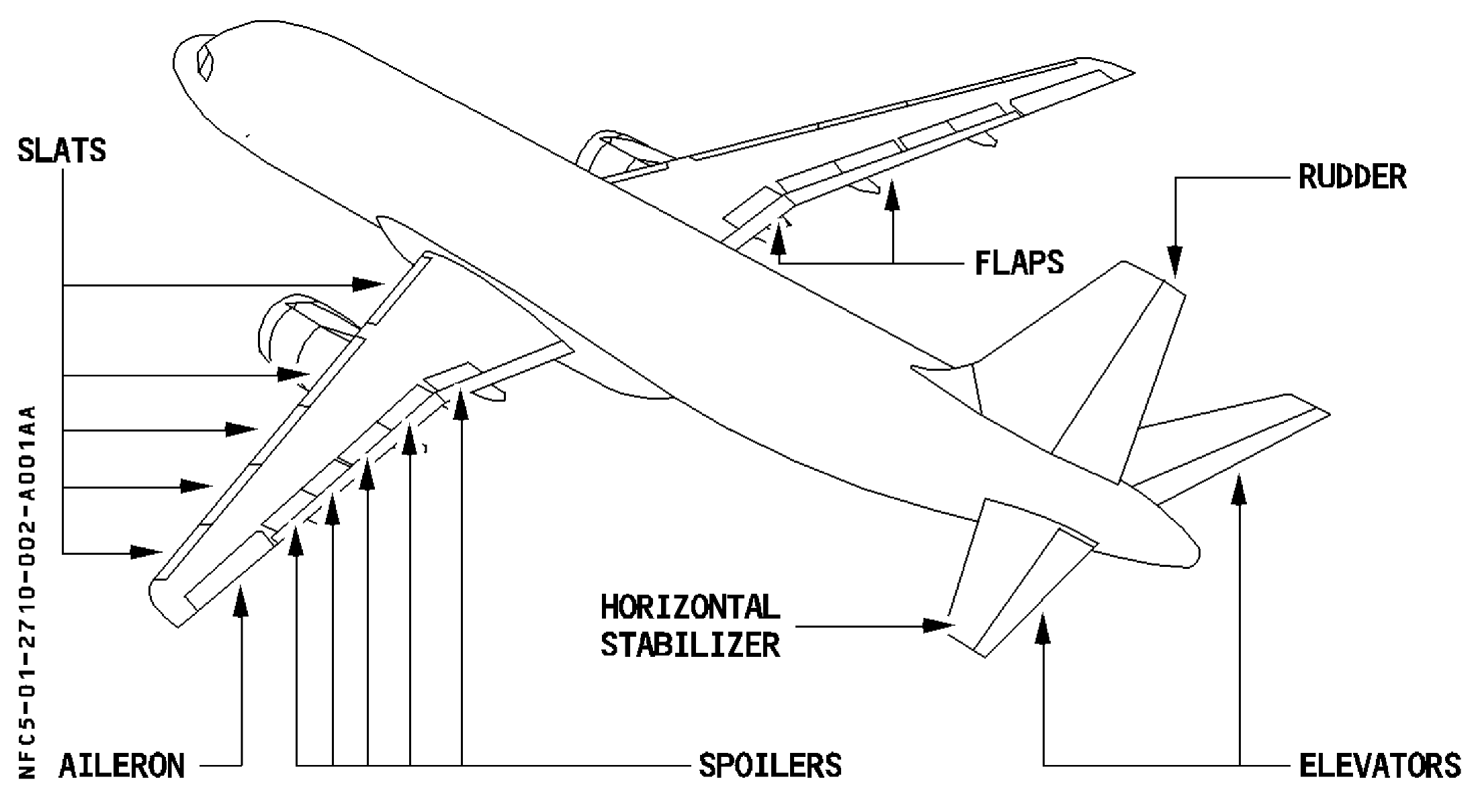
A320 flight-control surfaces in the original airframe drawing. [73, PDF p. 3]