ILS CAPTURE AND AUTOLAND CAPABILITY ARE SEPARATE ASSESSMENTS
For an ILS, identify the intended installation and compare frequency, identifier, course and aircraft position with the current chart. Displaying the raw scales through LS/ILS on the EFIS panel makes the signal information visible; APPR or LOC on the FCU requests the applicable guidance. Arm APPR for the cleared ILS method, or use the appropriate LOC selection for a localizer-only clearance. Follow arming, capture and tracking on the FMA while monitoring the raw deviations. The system can offer a signal or armed mode before the aircraft has actually captured it. [21, PDF pp. 159–162] [108, PDF pp. 2–5]
A coupled ILS does not by itself establish an autoland operation. Assess installed aircraft capability, actual system status, the appropriate autopilot arrangement, runway/ILS suitability and the applicable procedure and limitations. The supplied FCTM distinguishes fail-passive and fail-operational capability, including the consequences of a failure and the role of alert height. These concepts explain redundancy and decision logic; their old fleet-specific numeric minima and thresholds are not copied here as universal Fenix limits. Obtain the applicable values from the installed reference and the approach being practised. [21, PDF pp. 177–183]
The FMA capability annunciation is one part of the assessment. The manufacturer source notes that some equipment failures affecting landing capability are not fully represented by the displayed capability. Review the relevant status and required-equipment information before choosing the operation. Similarly, a simulated airport image does not establish that the ground installation is suitable for every automatic landing. During practice in good weather, be prepared for unsatisfactory guidance and take over or discontinue as required. The source explains why real ILS sensitive-area protection may differ when low-visibility procedures are not in force. [21, PDF pp. 179–183]
Brief the expected LAND, FLARE, thrust and rollout progression, required monitoring, takeover conditions and go-around strategy using the applicable standard. Minima must retain their barometric or radio reference; alert height is a different concept from a decision height. Review how a capability downgrade affects the prepared approach before it occurs close to the runway. An apparently smooth automatic descent cannot settle those decisions. The professional exercise is to recognise the relevant transition or failure in time to make the response already established by the briefing. [21, PDF pp. 177–183]
For a simulator comparison, retain one known runway and weather case, then introduce a documented equipment change before the approach preparation. Establish whether the operation remains appropriate and what changes in the briefing or minima are required. Do not turn a successful simulated landing into a claim of real-world operational approval. This guide has not verified a live Fenix test of every failure and downgrade combination. Where the source describes manufacturer behaviour and the simulator implementation remains untested, record that distinction with the exercise result. [21, PDF pp. 178–183] [127]
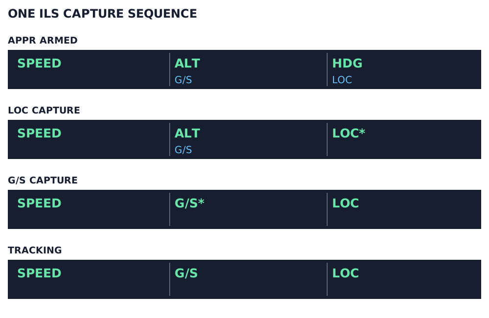
Illustrated ILS sequence, first three FMA columns only. Green: active; blue: armed. LOC* and G/S* are capture modes. Aircraft capability and AP/FD/A/THR-status columns are omitted. [21, PDF pp. 159–160]