A319/A320 FUEL FEED, TRANSFER AND COOLING
The A319/A320 reference system separates centre fuel, inner wing cells, outer wing cells and vent/surge spaces. Storage geometry supports engine feed and structural objectives; fuel in an outer cell is not simply another equal-sized bucket draining at the same rate. Pumps establish the required feed, while transfer valves move fuel between wing cells under defined logic. The FUEL page should be read as a distribution/flow picture as well as a total. A correct total can conceal a distribution or feed problem. [72, PDF pp. 2–6] [87, PDF pp. 96–99]
In the supplied pump-fed centre-tank standard, centre-pump pressure gives centre fuel priority when that feed is enabled. Wing pumps remain part of the arrangement and take over feed as the centre supply is removed. Automatic centre-pump inhibitions and recirculation-related logic belong to the specific source standard. Later production modifications can alter the design, so do not state that this exact centre-pump architecture applies to every real A320-family aircraft. Identify the simulated overhead and system page before using this reference sequence to explain a quantity trend. [72, PDF pp. 3–6, 11–12] [87, PDF p. 99]
Outer-to-inner wing transfer is different from crossfeed. Transfer changes the storage cell from which fuel becomes available; crossfeed connects engine-feed sides. The fuel-quantity system and low-level sensing also have separate roles. Quantity information supports mass and endurance monitoring, while low-level warning is designed as an independent indication in the supplied description. One cannot be dismissed because the other appears reassuring. A low quantity on one display, a feed warning and a measured fuel-used trend require correlated interpretation. [72, PDF pp. 5–10, 18–20] [87, PDF pp. 99, 103]
Fuel also performs thermal-management work. The reference descriptions include IDG cooling and recirculation, with engine-dependent differences; the IAE arrangement includes engine-oil cooling in that context. Recirculation returns and temperature logic can influence feed sequencing. This makes engine installation relevant even when both aircraft have familiar-looking wing tanks. Monitor fuel temperature, distribution and the actual feed path rather than assuming all fuel-related changes indicate consumption by the combustor. The source’s capacities, transfer thresholds and temperature limits remain effectivity-specific and are not adopted as universal current Fenix values. [72, PDF pp. 6–7] [87, PDF pp. 98–103]
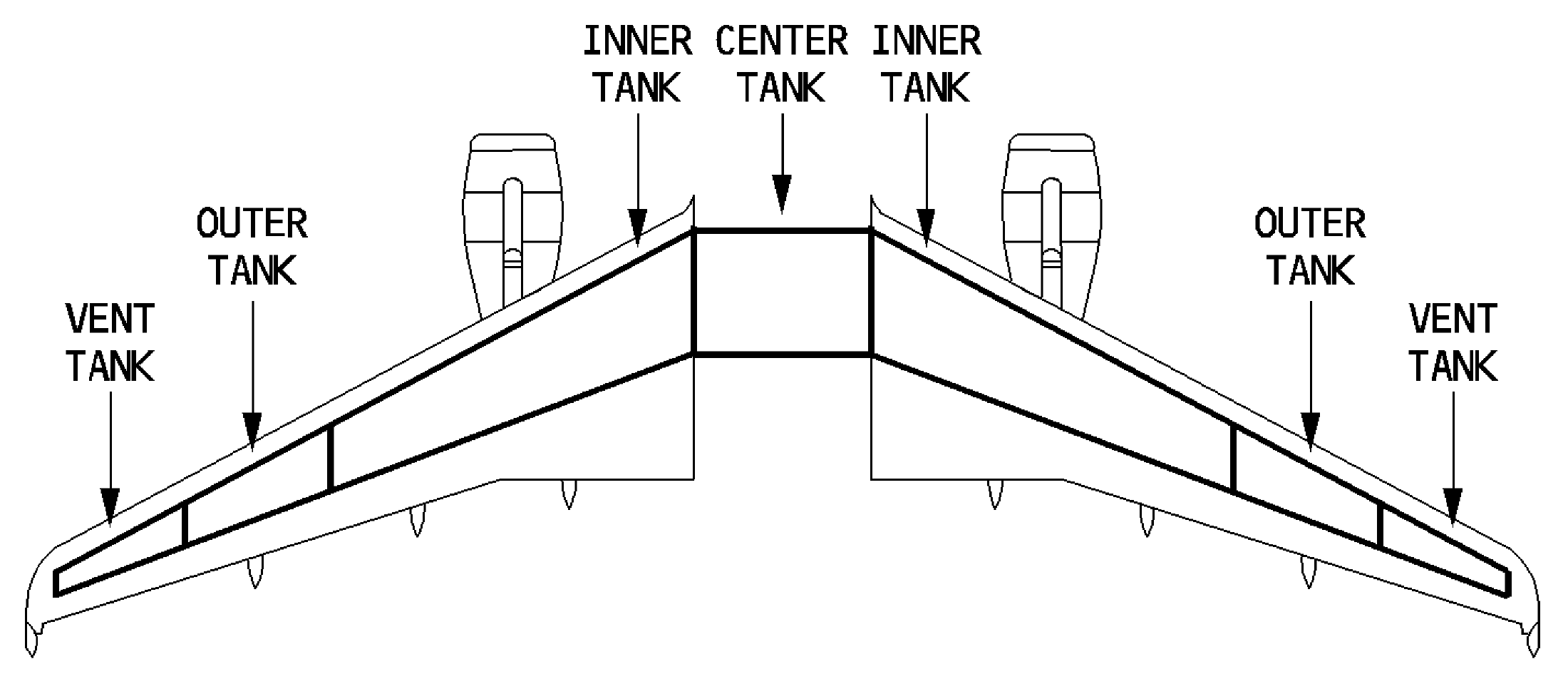
A319/A320 outer, inner and centre tank locations. [72, PDF p. 2]