ELECTRICAL GENERATION, CONTACTORS AND SOURCE PRIORITY
The normal electrical network is divided into AC and DC distribution rather than fed from one undifferentiated source. Engine generators supply their associated AC buses through generator line contactors. Transformer rectifiers convert AC to DC for the DC network. The AC essential bus is normally derived from the normal AC arrangement; the essential DC network has its own supply path. This separation makes the diagram diagnostic: a generator can be available while a contactor is open, or an AC supply can remain present while a conversion failure affects DC consumers. [62, PDF pp. 2–7]
Each engine generator is driven through an integrated drive, while the APU generator is driven by the APU. Their control units regulate output and protect the network by controlling connection. An external source passes through its own acceptance/protection arrangement. The installation does not parallel these normal generators. In normal operation the engine generators have priority; with engines stopped, selected external power has priority over the APU generator. Bus-tie logic permits an available source to supply the required network without treating every ready generator as simultaneously connected. [62, PDF pp. 4–8]
Loss of one engine generator is not the same event as loss of both normal AC buses. The supplied architecture replaces the failed source with the available APU generator or the other engine generator, with associated load shedding. Read generator output, connection and supplied buses together. A shed commercial load can be a consequence of preserved essential supply rather than an additional independent failure. Generator temperature, frequency/voltage indications and the source-to-bus path provide different evidence; none should be substituted for the whole electrical picture. [62, PDF p. 10] [87, PDF pp. 35–41]
A source transfer is best analysed in stages: replacement readiness, commanded disconnection of the former source, contactor reconfiguration and resulting bus supply. The engine-generators’ priority explains why a prepared APU may not carry the load before shutdown. At the stand, disconnecting a cable is a ground-service action after the aircraft supply has been confirmed. During a failure exercise, identify whether the loss is generation, connection, conversion or distribution before interpreting downstream messages. Similar-looking dark equipment can result from different points along that chain. [62, PDF pp. 6–14] [23, PDF pp. 1034–1038, 1161]
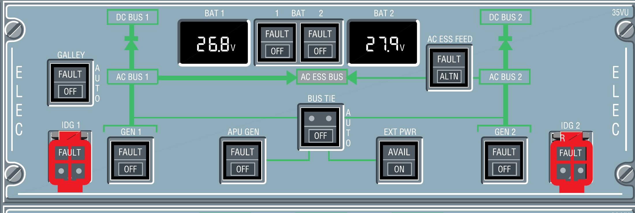
BAT 1, BAT 2, APU GEN and EXT PWR in the original overhead reference. [63, PDF p. 1]