HYDRAULICS: SOURCES, PRESSURE AND THE PTU
Green, Blue and Yellow are separate hydraulic systems with their own reservoirs. Pumps establish pressure and actuators use it to move the supplied equipment. Keeping the circuits distinct matters when interpreting a pressure change: shared mechanical assistance does not turn them into a common fluid system. [71, PDF pp. 2–3]
In the normal arrangement, engine 1 supplies the Green engine-driven pump and engine 2 supplies the Yellow engine-driven pump. Blue uses an electric pump; Yellow also has an electric-pump provision. On ECAM HYD, compare the available sources and resulting system condition with the current phase and normal configuration. [71, PDF pp. 2–3]
The PTU transfers mechanical power between Green and Yellow without transferring fluid. This explains both its usefulness and the limits of that assistance. During start or another supply transition, interpret PTU activity alongside the two systems' states. The familiar sound is information about the configuration, not a fault diagnosis on its own. [71, PDF p. 2]
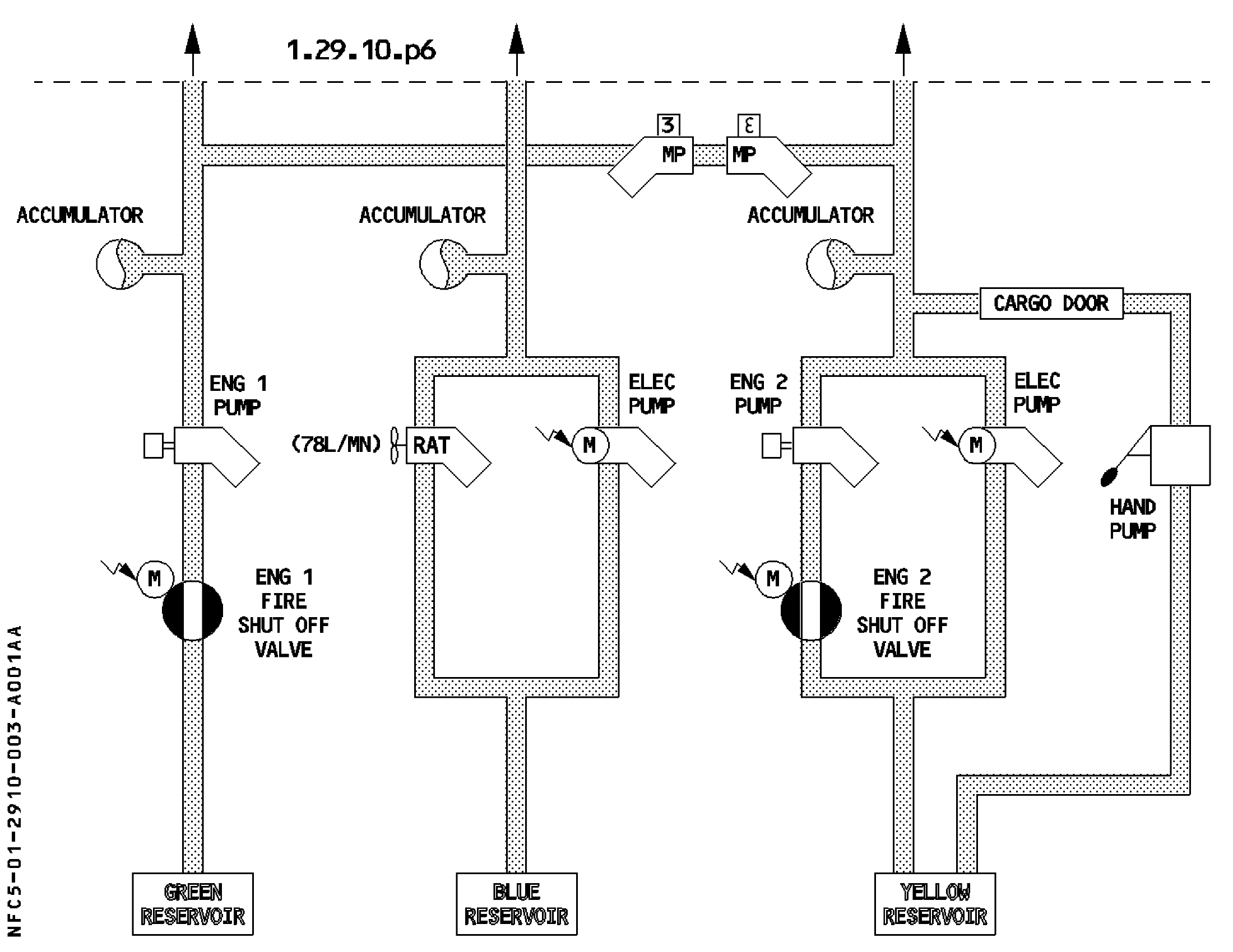
Green, Blue and Yellow hydraulic generation pumps. [71, PDF p. 4]
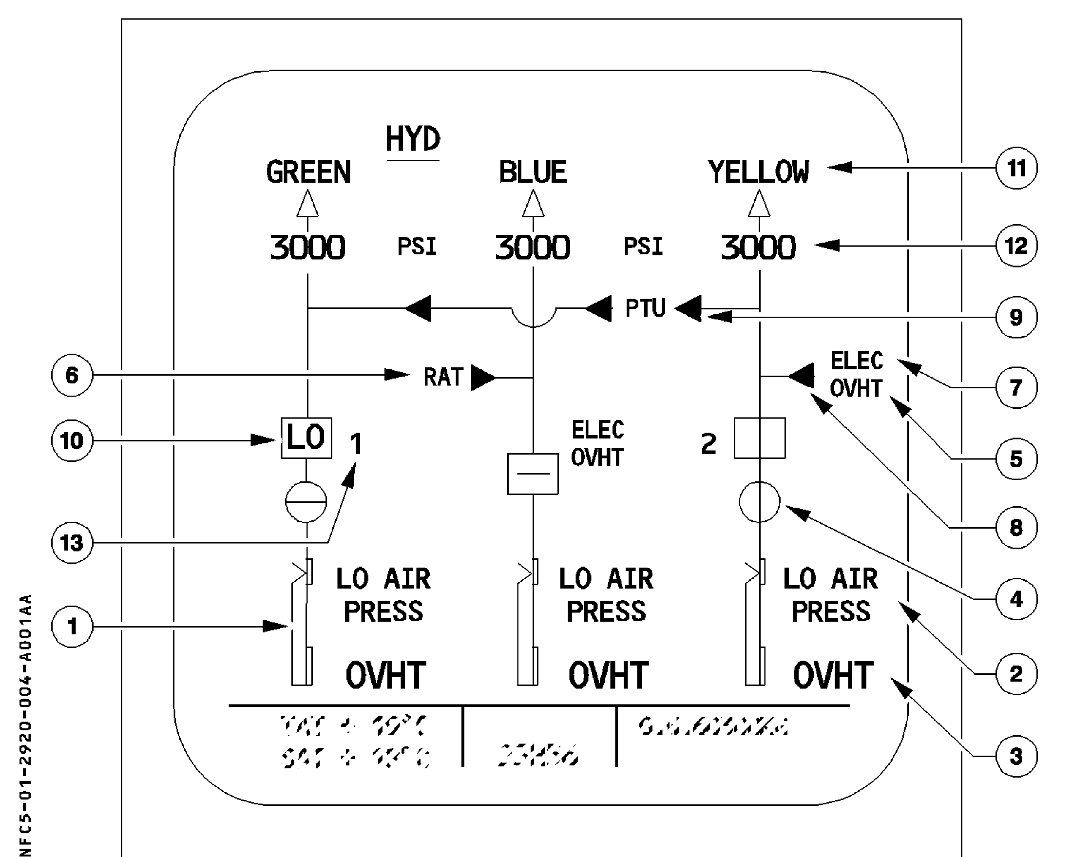
Original HYD display reference, including Green/Yellow PTU assistance. The numbered key follows; depicted figures and states are source examples. [71, PDF p. 11]
Key to the original diagram
1. Reservoir quantity
2. Reservoir LO AIR PRESS
3. Reservoir OVHT
4. FIRE VALVE
5. OVHT — electric pump
6. RAT
7. ELEC
8. YELLOW ELEC PUMP control
9. PTU control
10. ENG PUMP control and low-pressure indication
11. System label and pressure triangle
12. System pressure
13. PUMP
The fire-valve symbol at callout 4 means not fully closed when green in-line; an amber cross-line means fully closed. [71, PDF pp. 11–13]