ILS: IDENTIFICATION, CAPTURE AND MISSED-APPROACH SETUP
An Instrument Landing System, ILS, supplies two pieces of radio guidance towards a runway. The localizer, LOC, gives lateral alignment; the glideslope, G/S, gives the vertical approach path. First confirm the intended installation, frequency, identifier and course against the current chart. The identifier helps establish that the received signal belongs to the approach we intend to fly. Display the raw localizer and glideslope indications and compare them with the aircraft's position. A beam indication is useful evidence when it belongs to the right runway and we are approaching it with suitable geometry at the cleared altitude. [13, PDF pp. 159-162] [53, PDF pp. 2-4]
Two nearby controls do different jobs here. The LS display pushbutton, labelled ILS on some equipment, is on the EFIS display-control panel beside the FCU. It brings the landing-system scales and available identification into the PFD picture. EFIS is the Electronic Flight Instrument System; this panel controls parts of the instrument display. APPR and LOC on the FCU request guidance modes. Showing the scales helps you read the signal, while arming a mode asks the aircraft to use it. Neither action by itself proves that the correct signal is valid or that capture has occurred. [13, PDF pp. 159–162] [53, PDF pp. 2–4]
When cleared for the ILS and using the planned coupled method, arm APPR at the appropriate stage. Read the FMA as LOC and G/S progress from armed to capture and tracking. Arming prepares the modes; capture establishes that the guidance has begun acquiring the beam. Keep checking the raw deviations and actual turn or descent while that happens. A clearance for localizer only is different: use the appropriate LOC selection and retain the cleared vertical path. It does not give permission to follow the glideslope. The aircraft can offer guidance that we are not yet cleared to use. [53, PDF p. 5] [13, PDF p. 160]
Plan to intercept the glideslope from below with suitable cleared geometry. Once vertical capture is established, set the missed-approach altitude at the stage required by the normal procedure. That prepares the next flight path while the captured guidance continues the approach. Keep comparing the runway, chart, clearance, modes and raw indications as we descend. For a first Heathrow ILS, notice the sequence as it unfolds: lateral acquisition, vertical acquisition, then continued tracking towards the runway. Learning what each transition looks like makes the approach easier to monitor and makes an unexpected mode much easier to recognise before it has carried us far. [53, PDF p. 5]
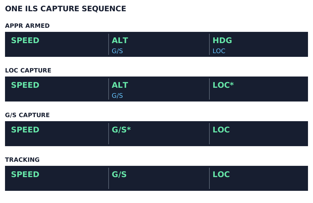
Illustrated ILS sequence, first three FMA columns only. Green: active; blue: armed. LOC* and G/S* are capture modes. Aircraft capability and AP/FD/A/THR-status columns are omitted. [13, PDF pp. 159–160]
IN PRACTICE: Capture the Heathrow ILS and confirm each handover
Before you begin: The selected runway/ILS and chart agree. The aircraft is approaching the localizer at the cleared altitude in a configuration and speed suited to interception.
1. Identify the aid you intend to use
Action. Compare the ILS frequency, identifier and course with the selected approach and chart. Press LS on the relevant EFIS controls and inspect the PFD ILS scales and identifier.
Check. The raw localizer/glideslope information is visible and refers to the intended installation. [13, PDF pp. 159-162] [26, PDF p. 474]
2. Prepare a sensible intercept
Action. Use the cleared route or vector to approach the localizer with an appropriate intercept geometry. Plan to intercept the glideslope from below on this normal exercise.
Check. The aircraft can capture the lateral course and then the vertical beam without a rushed descent from above. [13, PDF pp. 159-162] [14, PDF pp. 1091-1110]
3. Arm the clearance actually received
Action. When cleared for the ILS approach, press APPR and confirm LOC and G/S armed on the FMA. For a localizer-only clearance, use LOC. Configure the autopilot arrangement for the briefed coupled approach.
Check. The armed modes correspond to the clearance; vertical capture has not been armed merely because a localizer intercept was requested. [13, PDF p. 160]
4. Watch the localizer capture
Action. Check LOC* and then LOC, the raw deviation trend and the actual turn onto the final approach course.
Check. The aircraft has captured the intended lateral beam and is tracking the runway course. [13, PDF pp. 159-162] [14, PDF pp. 1091-1110]
5. Watch the glideslope capture
Action. Monitor G/S* and then G/S, the glideslope deviation and the actual descent. Once glideslope capture is confirmed, set the briefed missed-approach altitude on the FCU as required by the normal procedure.
Check. The vertical beam is captured, and the altitude window is prepared for a possible go-around without interrupting the established glideslope guidance. [13, PDF pp. 159-162] [14, PDF pp. 1091-1110]
6. Keep checking after capture
Action. Continue comparing raw deviations, FMA modes, speed and the outside/runway picture as visibility permits. Read the displayed approach capability against the planned minimum and autopilot arrangement.
Check. The approach remains correctly guided and suitable for the intended landing method. Capture has begun a monitoring task rather than ended it. [13, PDF pp. 159-162] [13, PDF pp. 177-183]
Complete when: The aircraft is tracking the intended ILS, with lateral and vertical capture confirmed and the missed-approach altitude prepared.