CFM56-5B AND IAE: INTERPRET THE INSTALLED ENGINE
Our exercise aircraft has CFM56-5B engines. Their primary thrust reference is N1, the speed of the low-pressure rotor, which includes the large fan at the front. The display also supplies N2, exhaust-gas temperature, fuel flow and oil information. Keep that supporting picture in view. A thrust reference becomes much more informative when we understand what the rest of the engine is doing alongside it. [28, PDF pp. 4-6]
N1 and N2 are rotor-speed percentages. Each uses its own reference speed: N1 for the low-pressure assembly, N2 for the high-pressure core. They therefore have different normal values and need not resemble one another at idle. The percentages describe rotational speed. They are not two fuel-gauge-style measures of how much thrust remains available. During the start, watching N2 increase is how we first recognise the starter turning the core. [12, PDF p. 3] [12, PDF pp. 36-50]
Next come the combustion and lubrication clues. FF is a flow rate, so keep its displayed units separate from the total fuel quantity aboard. EGT is exhaust-gas temperature. The training material calls for increasing oil pressure during start and a comparison of relative engine vibration afterwards. Rotation, fuel, temperature and lubrication build a fuller picture together than any one of them can provide alone. [13, PDF pp. 103-106]
At stable idle, take an unhurried look across both engines. Compare the achieved indications and the displayed rating or limit with the intended operating state. Repeat that pattern during later taxi-power changes and takeoff stabilisation. Familiarity develops from those comparisons under the actual conditions. An idle figure remembered from a different airfield or configuration is only a fragment of the picture we need today. [12, PDF pp. 36-50] [13, PDF pp. 103-106]
An aircraft fitted with IAE V2500 engines uses EPR, engine pressure ratio, as its primary thrust reference. This ratio concerns engine pressures; it is a different measurement from N1 rotor speed. The IAE still has other engine indications to monitor. Recognise the installation you have selected, use the corresponding procedure, and expect its display and starting characteristics to have their own details. [11, Chapter FADEC]
Fenix V3's presentation describes independent engine-control units and differences in fuel-control and electrical architecture. It also discusses the selectable IAE pre-start motoring option. That can include intended rotation before the later part of the start develops. Compare the actual engine and selected option with their procedure, rather than expecting the timing of a familiar CFM start on every installation. [11, Chapter FADEC]
The represented machinery also takes time to respond to a thrust change. Follow what both engines achieve as the command develops, particularly during taxi, takeoff stabilisation and thrust reduction. Equal lever positions do not complete that check for us. As you fly more sectors, the collection of abbreviations starts becoming an engine you can follow: what is turning, what is burning, and how the response is developing on each side. [12, PDF p. 3] [11, Chapter FADEC]
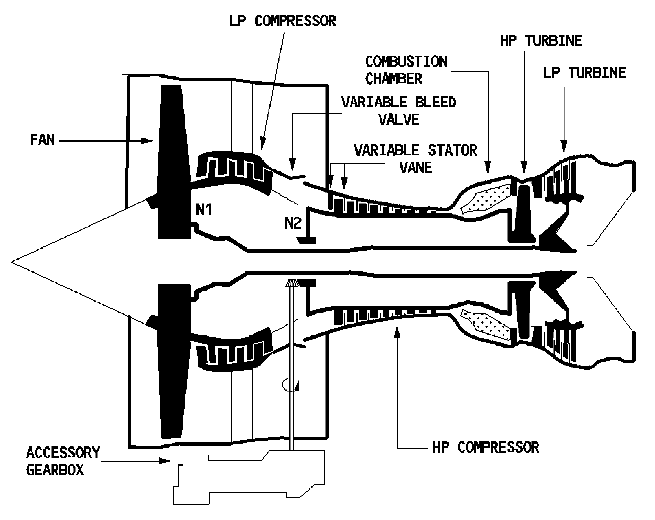
CFM56-5B cross-section with the N1 and N2 spool references. [12, PDF p. 3]
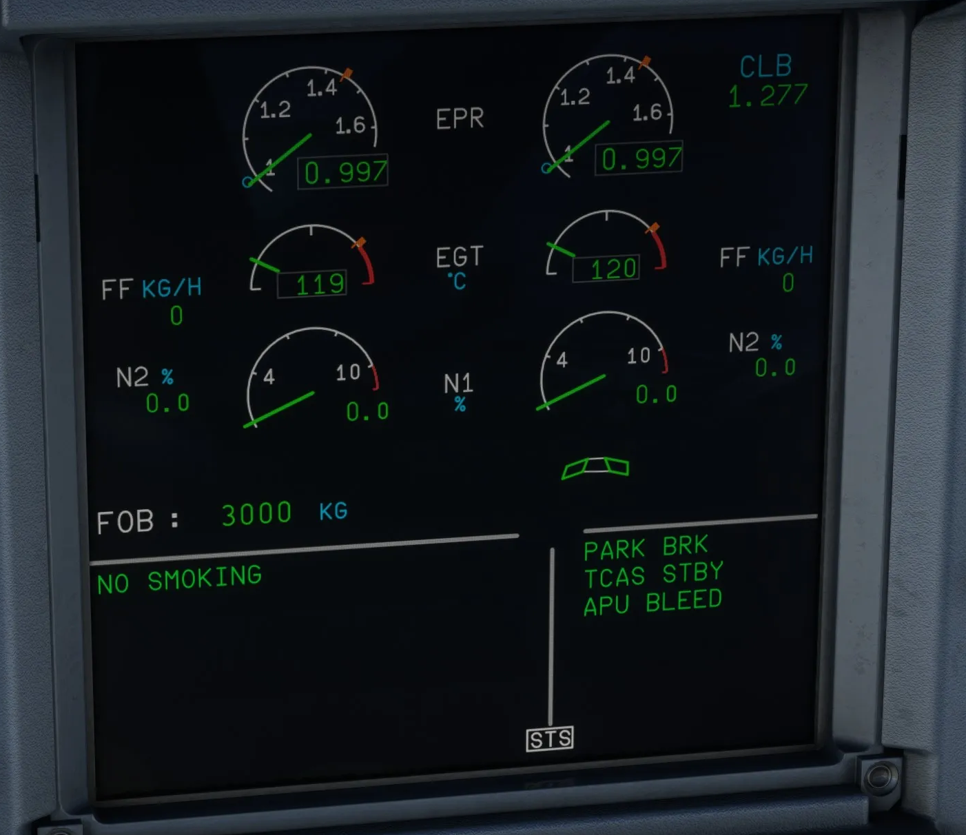
Original Fenix IAE E/WD with EPR as the primary thrust reference. Engines are stopped: N1, N2 and fuel flow are zero. [30, Source illustration]