ENGINE START: FOLLOW THE SEQUENCE TO STABLE IDLE
Engine start is a sequence we can follow on the display. Selecting IGN/START prepares the start arrangement; the intended ENG MASTER command begins the selected engine's sequence in accordance with the procedure. Look for the first physical response rather than assuming the engine has started because a switch moved. The air starter begins turning the high-pressure rotor, whose speed is shown as N2. [28, PDF pp. 4-5] [13, PDF pp. 103-106]
The automatic start is managed by the FADEC, Full Authority Digital Engine Control. Think of it as the engine's control system, scheduling the required engine actions and monitoring its operation. Our job is to understand and observe the sequence it is carrying out. That begins with rotation: N2 should develop as the starter works. Each later indication adds another piece of evidence about the start. [28, PDF pp. 4-5] [13, PDF pp. 103-106]
Fuel flow, often labelled FF, shows fuel being supplied to the engine. Ignition and the fuel schedule establish combustion, followed by a rise in EGT, exhaust-gas temperature. N2 describes rotor motion; EGT describes temperature at the monitored exhaust-gas station. Reading them together helps us distinguish the turning engine from the engine in which combustion has begun. [28, PDF pp. 4-5]
As the sequence develops, include N1, the low-pressure rotor speed, and the oil indications. Oil pressure belongs to the lubrication picture. These indications have different meanings and normal responses, so they are checked as a group. You are looking for a sensible progression towards stable operation, rather than one particularly reassuring number on an otherwise unexplained display. [28, PDF pp. 4-5]
At the appropriate point, the starter disengages and the engine settles towards stable idle. The loaded engine's normal procedure and limits establish that completion; a spinning fan alone does not. Once the first start is complete, begin the other as required and continue monitoring both. An unexpected temperature or acceleration trend calls for the applicable procedure, with the simulator paused for study when needed. [14, PDF pp. 1039-1047] [14, PDF pp. 1048-1050]
Return the mode selector to NORM at the proper stage and continue the after-start work. Different engine installations and selected options can change details of the sequence, so we will compare the CFM and IAE indications next. The practical exercise keeps the same useful structure throughout: make the intended command, observe the expected response, and establish completion before moving to the next task. [14, PDF pp. 1039-1047] [14, PDF pp. 1048-1050]
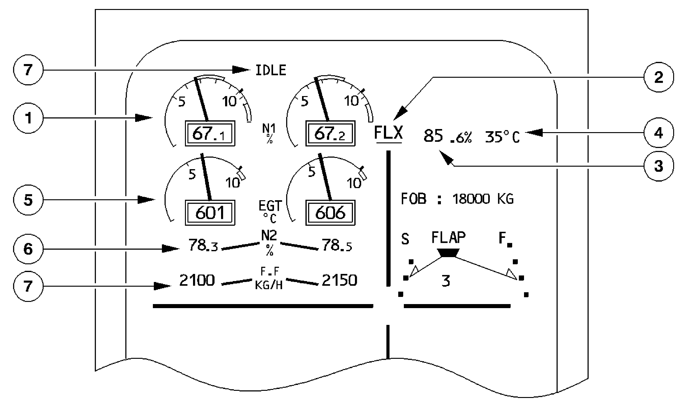
CFM primary-parameter layout: N1, EGT, N2 and fuel flow. Original composite training schematic; its figures are not a coherent normal-idle snapshot or operating targets. [12, PDF p. 40]
IN PRACTICE: Start engine 2, then recognise a completed start
Before you begin: The Before Start preparation is complete, APU bleed pressure is available, thrust levers are at IDLE and the normal automatic-start method is being used.
1. Select the starting mode
Action. Turn the ENG MODE selector to IGN/START and observe the engine display before operating a master switch.
Check. The start-related indications are available. This mode selection prepares the control system; it has not yet commanded an engine to run. [13, PDF pp. 103-106] [14, PDF pp. 1039-1047]
2. Request engine 2
Action. Set ENG MASTER 2 to ON. Follow engine 2 on the display; leave the other engine for its own start after this one is established.
Check. The start valve opens and N2 begins to rise as the starter turns the high-pressure spool. [13, PDF pp. 103-106] [14, PDF pp. 1039-1047]
3. Follow the sequence, not just one number
Action. Watch the ignition indication, fuel flow and EGT response as N2 continues to increase. Include N1 and the oil-pressure rise in the scan.
Check. Rotation is followed by fuel and ignition, then a temperature response and increasing fan speed. The indications form a plausible start sequence. [13, PDF pp. 103-106]
4. Recognise the handover from starter to engine
Action. Continue watching until the start-valve and ignition indications complete their normal sequence and the engine settles at idle or displays AVAIL. Compare the stabilised parameters instead of using elapsed time as the completion test.
Check. The engine has become self-sustaining and the starter is no longer driving it. The indications are stable enough to begin the second start. [13, PDF pp. 103-106] [14, PDF pp. 1039-1047]
5. Repeat the observation for engine 1
Action. Set ENG MASTER 1 to ON and repeat the same N2, ignition, fuel, EGT, N1 and oil-pressure scan on engine 1.
Check. The second engine completes its own start. Similar master-switch actions have been followed by two separately monitored results. [13, PDF pp. 103-106] [14, PDF pp. 1039-1047]
6. Read both engines together
Action. When both are stable, compare the two columns, including the relative vibration indications. Finish the engine-start check before changing to after-start tasks.
Check. Both engines show a normal, stabilised operating picture. An unexplained disagreement has not been hidden by concentrating on the second start alone. [13, PDF pp. 103-106] [14, PDF pp. 1039-1047]
Complete when: Both engines are stable and the automatic-start sequence is complete. Continue with the normal after-start flow; an unsuccessful start belongs to the indicated ECAM procedure, not to an improvised repeat of this exercise.