STARTING THE APU AND FINDING OUT WHAT IT SUPPLIES
The Auxiliary Power Unit, or APU, is the small gas turbine in the tail. Two of its outputs matter during preparation: electricity from its generator and compressed air for the pneumatic system. Pneumatic simply means using air pressure. Keeping those outputs separate explains several otherwise puzzling situations. The APU can be running and available while the electrical buses remain on ground power. It can also be ready for electrical use without the required bleed-air path having been established for an engine start. One successful start does not by itself confirm every use you plan to make of it. [24, PDF pp. 2–3] [27, PDF pp. 2]
Complete the normal preparation and required fire-test sequence before requesting the start. MASTER SW prepares the APU system; START begins the starting sequence. Follow the APU page as the intake opens and the unit accelerates, then recognise the AVAIL indication. A request and a completed result are different stages, so give the sequence time to develop. You are watching the machine establish a running condition. Repeatedly pressing controls adds little information compared with reading the indications that show where the process has reached. [19, PDF p. 4] [24, PDF pp. 5–6]
Now check the output you actually need. For electricity, establish generator readiness and confirm the source supplying the aircraft on ELEC. For an APU-assisted engine start, establish APU BLEED and the usable air route shown on the relevant system page. Bleed air is compressed air supplied from the source to the aircraft's pneumatic consumers. After the engines take the required loads, remove APU use through the normal procedure and allow its shutdown sequence to finish. Check the receiving systems as well as the unit you are shutting down, so the transfer remains understandable. [24, PDF pp. 5–6] [27, PDF pp. 7–8]
Our first useful APU exercise ends with three separate answers: has the APU reached AVAIL, what is supplying the electrical buses, and is the intended pneumatic supply available? At the gate, the answer to the second question may still be external power. That can be exactly right. You now have enough information to understand the subsequent handover instead of waiting for every diagram to change at the moment the APU becomes audible. [24, PDF pp. 2–3] [27, PDF pp. 2]
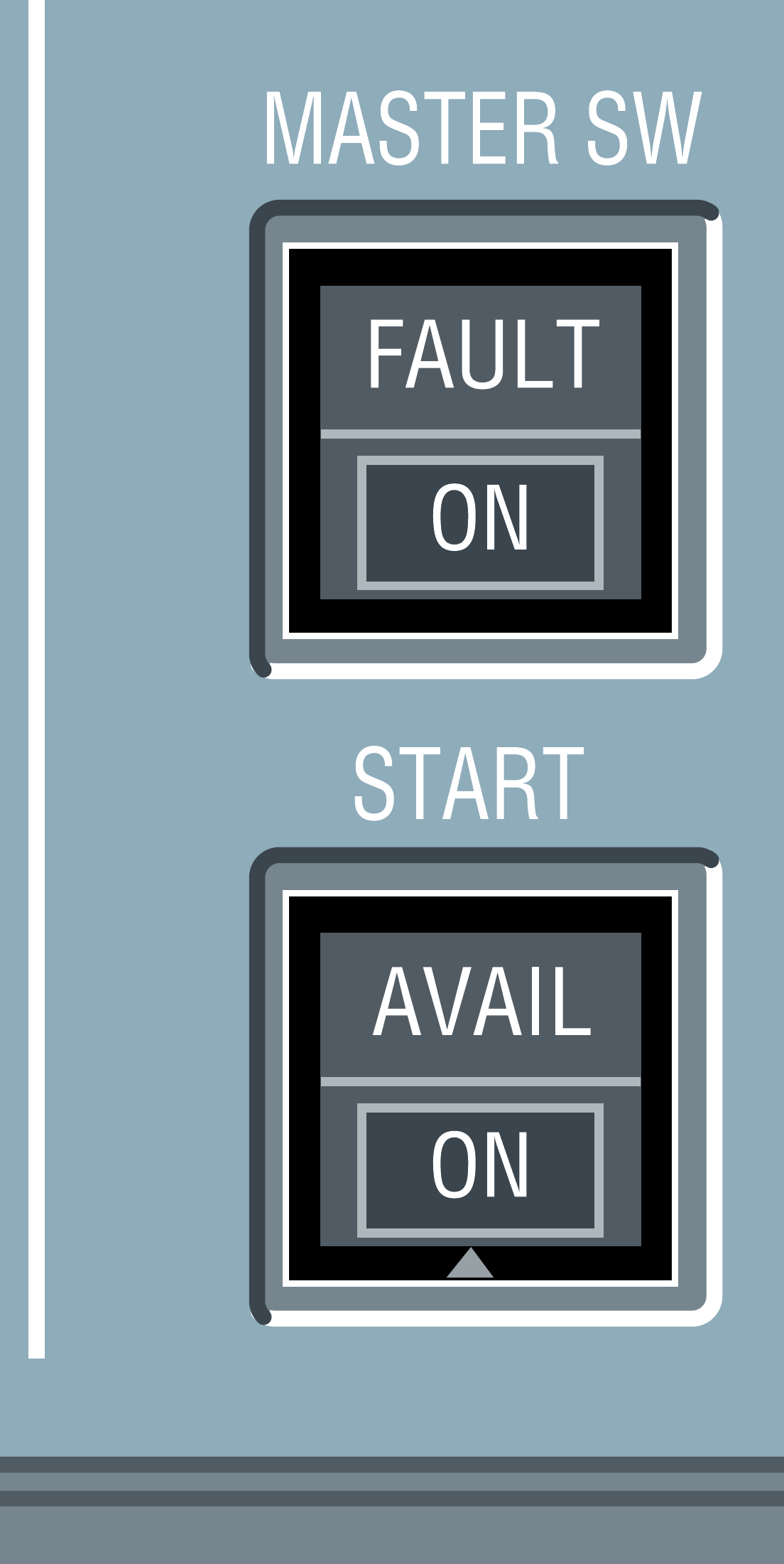
APU MASTER SW and START controls. [23, PDF p. 1]
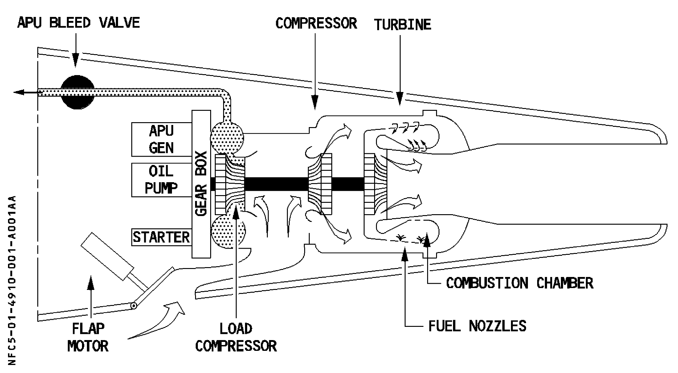
APU compressor, turbine, generator and air path in the original source. [24, PDF p. 2]
IN PRACTICE: APU: prepare, start, then identify the outputs
Before you begin: Stable electrical supply, secure stand and normal APU fire-test preparation complete. The area/service situation permits an APU start.
1. Confirm the starting state
Action. Check the guarded APU FIRE control in its normal position and that the normal APU fire test has been completed. Review the intended use of the APU: electrical supply, bleed air, or both.
Check. The start has a defined purpose and the required normal preparation is complete. [14, PDF p. 989]
2. Select MASTER SW
Action. Select APU MASTER SW ON. Observe the panel indication and the APU information shown on ECAM; call the APU page if it is needed for monitoring.
Check. The APU preparation sequence has begun and its monitoring information is available. [24, PDF pp. 5-6] [14, PDF pp. 990,992]
3. Request the start
Action. Select APU START and watch the sequence. Follow inlet-flap/open information, rotor-speed increase and EGT response on the APU page as displayed by the installed simulation.
Check. The start is progressing and its indications make sense together; the start request is not being mistaken for completed availability. [24, PDF pp. 5-6] [24, PDF pp. 8-9]
4. Wait for AVAIL
Action. Continue monitoring until the aircraft indicates APU AVAIL. Compare the panel and ECAM state before asking the APU to support the next part of the preparation.
Check. The APU has reached its available state. No fixed demonstration timing has been substituted for the actual completion indication. [24, PDF pp. 8-9] [14, PDF pp. 988-999]
5. Check electricity and air separately
Action. Use ELEC to identify whether APU GEN is actually supplying; external power may still have priority. If bleed air is required, continue with the pneumatic-supply workshop and verify that path on BLEED.
Check. Electrical availability, actual bus supply and pneumatic supply are individually understood. [22, PDF p. 6] [24, PDF pp. 2-4] [27, PDF p. 7]
Complete when: The APU is AVAIL and its electrical and pneumatic outputs have been checked separately for the next planned task.