HYDRAULICS: THE FORCE BEHIND THE MOVEMENT
An electrical signal can request movement, but equipment such as flight-control surfaces also needs a source of force. Hydraulic systems provide that force by using pressurised fluid. Pumps create the pressure, and actuators use it to move the equipment supplied by that circuit. The Airbus has three separate systems called Green, Blue and Yellow, each with its own reservoir. The colours identify circuits, not stages of one shared tank. Keeping them separate in your mind makes it easier to understand why a change in one pressure indication does not automatically explain the state of the others. [31, PDF pp. 2–3]
In the normal arrangement, engine 1 drives the Green system's engine-driven pump, and engine 2 drives the Yellow system's engine-driven pump. Blue uses an electric pump; Yellow also has an electric-pump provision. On ECAM HYD, look at the sources available in the aircraft's present state and the resulting pressure indications. HYD is the hydraulic-system page. A stopped aircraft at the gate does not have the same operating sources as one with both engines running. Read the page against the phase and normal configuration, rather than expecting every indication to remain unchanged throughout preparation. [31, PDF pp. 2–3]
The Power Transfer Unit, or PTU, links Green and Yellow through mechanical power. It allows one side to assist the other without moving hydraulic fluid from one circuit into the other. That last distinction matters: assistance is not the same thing as sharing a reservoir or replacing missing fluid. During an engine start or another supply transition, PTU activity can be part of the changing system picture. If you hear its characteristic sound, include the Green and Yellow states in your interpretation. The sound alone cannot tell you whether you have a normal transition or a problem. [31, PDF p. 2]
Use the diagram to keep two questions separate. How much fluid is in the reservoir, and what pressure has the system established? Quantity and pressure describe different parts of the story. Then connect the available pump to the circuit it supplies. The original HYD illustration includes a numbered key, so you can identify a symbol without guessing. You are learning to read the sources and resulting state; there is no need to turn every unfamiliar symbol into a switch experiment. [31, PDF pp. 2–3]
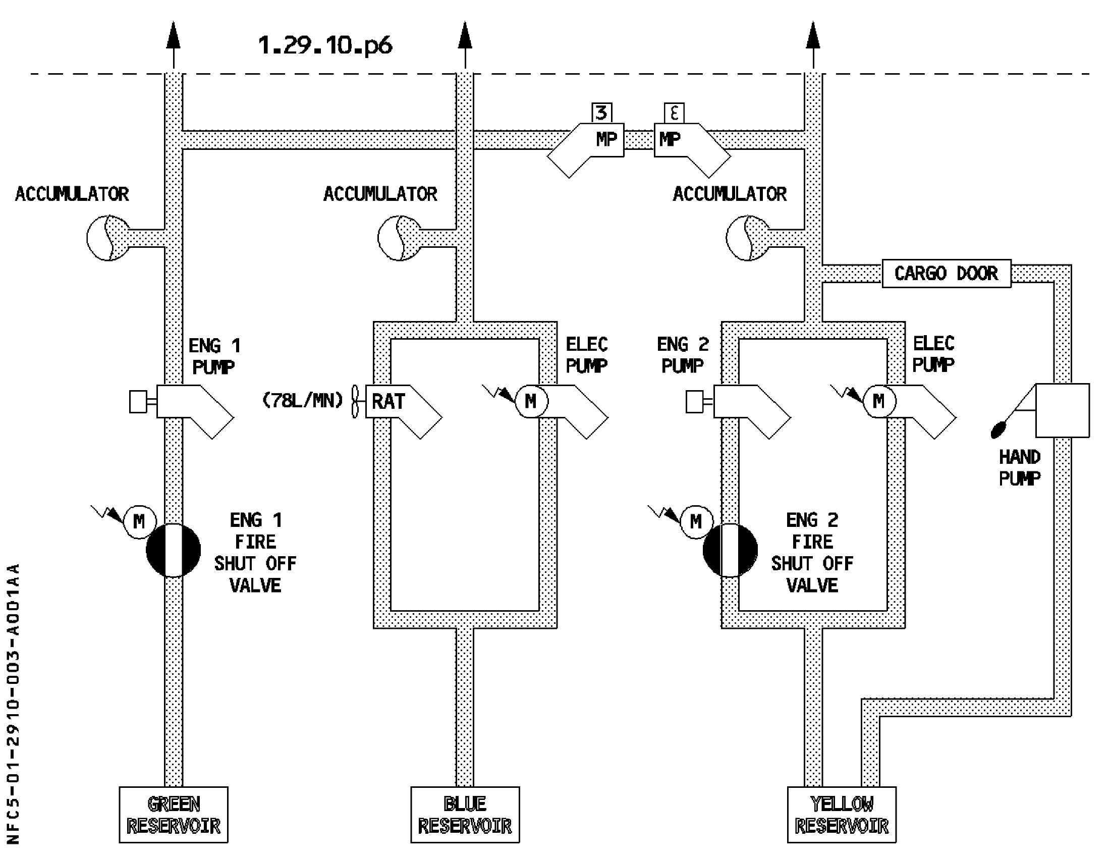
Green, Blue and Yellow hydraulic generation pumps. [31, PDF p. 4]
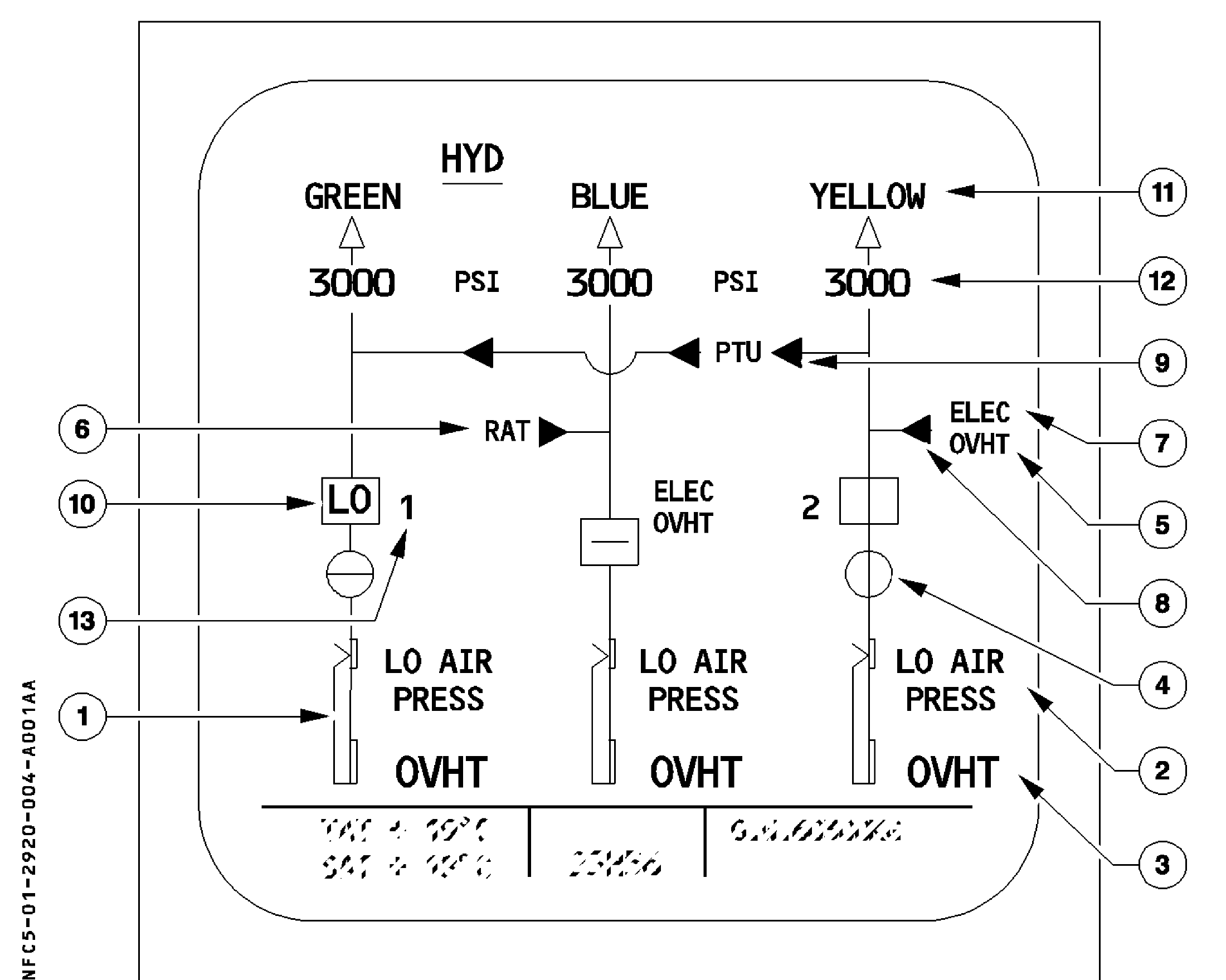
Original HYD display reference, including Green/Yellow PTU assistance. The numbered key follows; depicted figures and states are source examples. [31, PDF p. 11]
Key to the original diagram
1. Reservoir quantity
2. Reservoir LO AIR PRESS
3. Reservoir OVHT
4. FIRE VALVE
5. OVHT — electric pump
6. RAT
7. ELEC
8. YELLOW ELEC PUMP control
9. PTU control
10. ENG PUMP control and low-pressure indication
11. System label and pressure triangle
12. System pressure
13. PUMP
The fire-valve symbol at callout 4 means not fully closed when green in-line; an amber cross-line means fully closed. [31, PDF pp. 11–13]