CFM56-5B AND IAE: INTERPRET THE INSTALLED ENGINE
On the CFM installation, N1 is the primary thrust reference. Read EGT, N2, fuel flow and oil indications alongside it. A thrust indication is meaningful within that operating picture, particularly during start, stabilisation and a commanded change in thrust. [28, PDF pp. 4-6]
N1 and N2 describe the low- and high-pressure rotors as percentages of their respective reference speeds. The values are therefore different measures, not two interchangeable percentages of available thrust. Their relationship during acceleration and idle should be interpreted against the CFM installation rather than an expectation that the numbers ought to resemble one another. [12, PDF p. 3] [12, PDF pp. 36-50]
Follow fuel flow, exhaust-gas temperature and lubrication indications through the sequence. The training manual calls for rising oil pressure during start and a comparison of relative engine vibration after start. Read these with the rotor trends to establish the developing combustion and mechanical picture. [13, PDF pp. 103-106]
At stable idle, compare achieved indications, the displayed rating or limit and the corresponding engine. Continue the same crosscheck during taxi-power changes and takeoff stabilisation. Build familiarity with the normal picture under the actual conditions; a remembered idle figure from another airfield or configuration is not the complete expectation. [12, PDF pp. 36-50] [13, PDF pp. 103-106]
The IAE installation uses EPR as its primary thrust reference and has its own starting characteristics. V3's presentation describes independent engine-control units and differences in fuel-control and electrical architecture, including a selectable IAE pre-start motoring option. Judge the sequence against the installed engine and selected option rather than importing CFM timing assumptions. [11, Chapter FADEC]
Allow the represented rotating machinery and control system time to respond to a thrust change. Compare what both engines achieve during taxi, takeoff stabilisation and thrust reduction. Equal lever positions do not remove the need to investigate an unexplained difference in the resulting indications. [12, PDF p. 3] [11, Chapter FADEC]
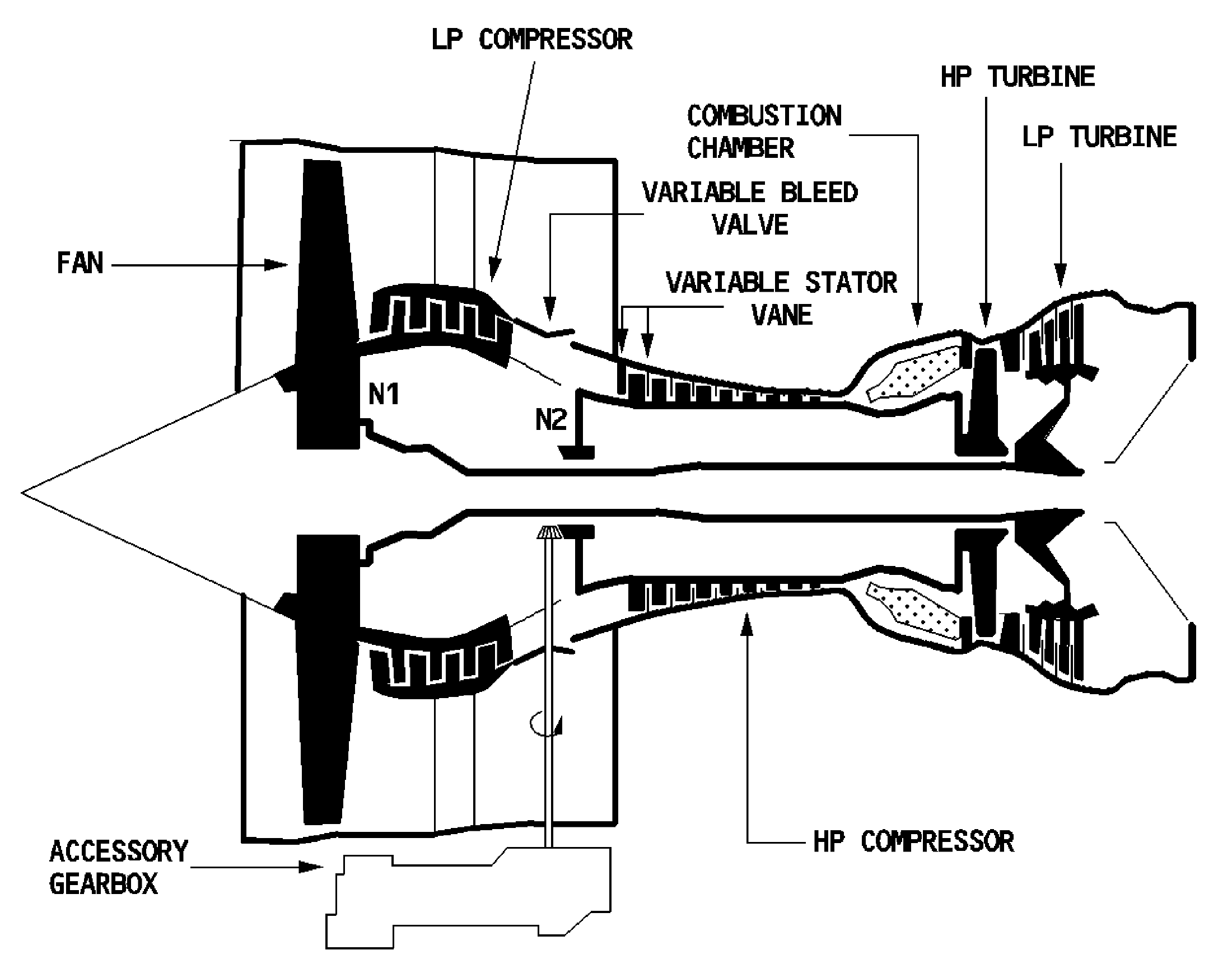
CFM56-5B cross-section with the N1 and N2 spool references. [12, PDF p. 3]
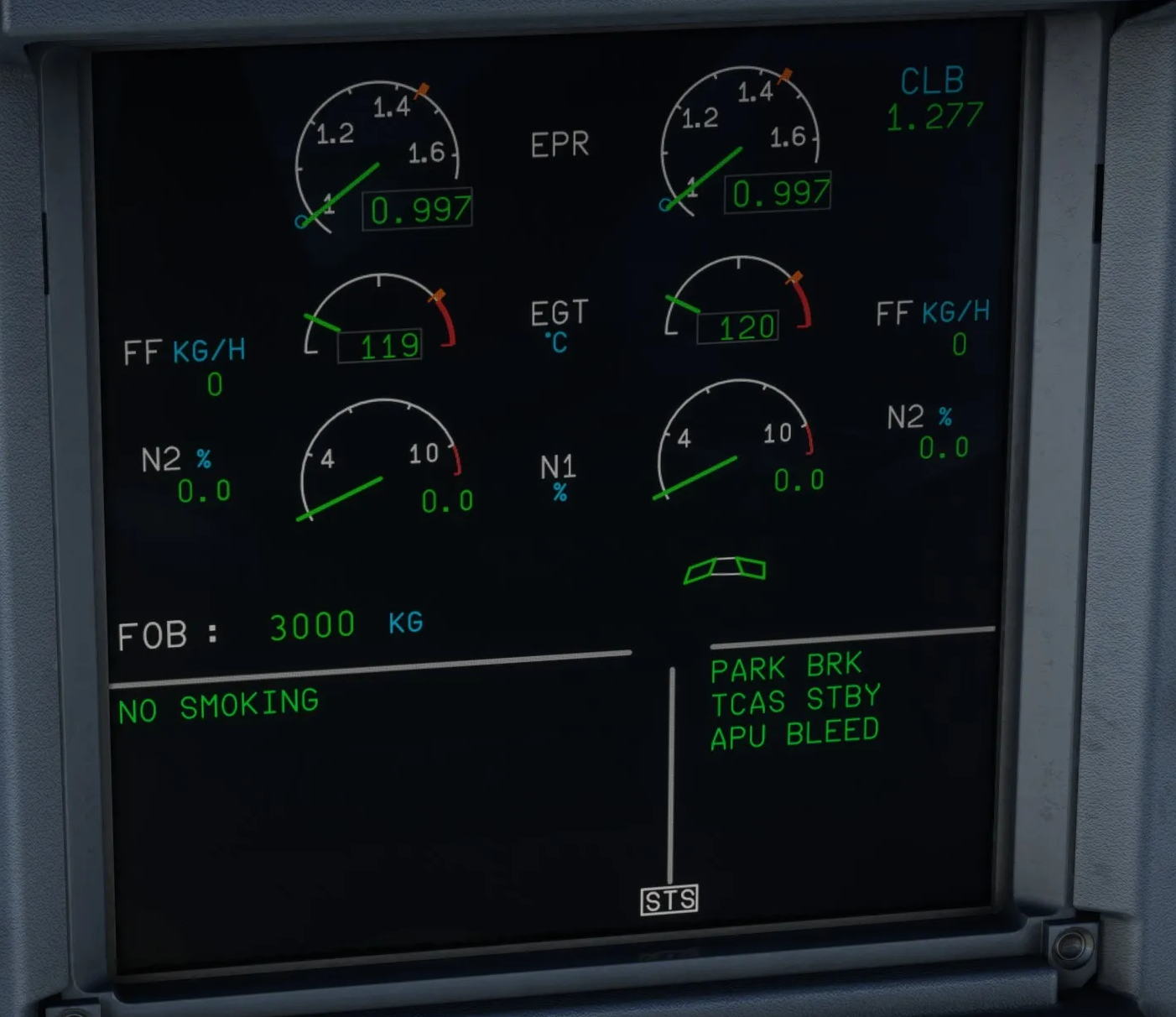
Original Fenix IAE E/WD with EPR as the primary thrust reference. Engines are stopped: N1, N2 and fuel flow are zero. [30, Source illustration]